

Chapter 4 – wiring:
This chapter is about the wiring of all electronic components inside the Raspberry PI RC car. The focus of this chapter is to connect the L298 H-Bridge with the Raspberry Pi. To wire everything together the best way is to use female to female jumpers. This type of wire works best, save without loos contacts and easy. To power up the Raspberry Pi we need an USB plug with a micro USB connector. To supply the motor driver we need a 6V to 9V charger with 2A. Maybe you can use an old smartphone charger with 5V and 1 A. This would be good enough for the first tests.
ATTENTION:
From my experience the 5V out from the L298 H-Bridge is not stable enough to supply the Raspberry Pi with energy. The variations are to strong and in my case the Raspberry Pi always crashed while switching on the four motors.
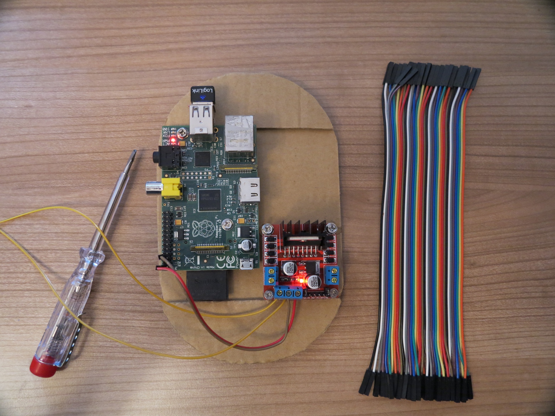
Components you need:
- Wire – Female to Female Jumper
- 1 x charger 6V to 9V with 2 A for the motor driver
- 1 x charger 5V micro USB for the Raspberry Pi
- a small screwdriver
- pliers
- soldering iron
Raspberry Pi GPIO connectors
ATTENTION:
It is important to note the following points and to wire everything very carefully together not to burn the Raspberry Pi.
Hint 1: The Raspberry Pi is a 3.3V Linux computer. You should not use higher voltages then 3.3V on the GPIO pins.
Hint 2: The GPIO connectors are not buffered and not secured against wrong wiring. If you make a mistake and connect a wire wrong the Raspberry Pi will never forgive this failure. Take care not to fry the little computer with a short circuit.
Hint 3: There are differences in the assignment of the GPIO ports between the version A, B and B+ of the Raspberry Pi. For this HowTo papers I am using the Raspberry Pi B with 512 MB RAM. To wire everything correct it is important to know the differences in the versions which are available. For each version a GPIO diagram is available in the internet.
Raspberry PI – remote controlled car with a Raspberry Pi female-to-female jumper wires

Build your own robot car with the Raspberry Pi!
Step by step to your own robot carThis book guides you in two parts through the project phases with the aim of building an individual, autonomously driving robot car. In the first part of the book you will learn the basics of robotics and the interaction of hardware, electricity and software. You build the chassis and wire the individual components - details can be found in the appropriate, richly illustrated chapters. An introduction to software installation and programming with Scratch and Python completes the first part. You do not need any previous knowledge in robotics and programming. In the second part of the book, you will familiarize yourself with the sensors required for autonomous driving. With the acquired knowledge you can individualize and further develop your robot car as you wish. The knowledge you acquire in this book will enable you to implement your own projects with the Raspberry Pi.
This book offers you that:
- Simply get into robotics with the Rasperberry Pi without prior knowledge
- Numerous illustrations, tables, circuit diagrams
- Information boxes with useful tips also for other Raspberry Pi projects
- Project code with syntax highlighting
- Two car projects: remote-controlled robot car via WLAN and self-driving car
- Hardware tips and recommendations for suitable accessories - Extensive project material as download: Raspbian image, parts list, chassis artwork and code
- Special features: Easy and robust cabling, use of high-precision time-of-flight laser distance measurement sensors, introduction to servo motors and suitable servo controllers, control via gamepad, use of an OLED display
Ingmar Stapel studied computer engineering and is currently working internationally as IT project manager and enterprise technical architect; in addition, he has been intensively involved with Raspberry Pi and robotics for years. He likes to share this knowledge with interested people from the tinkering scene at meet-ups on robotics. On his private blogs he also writes about many current technology trends.
Logical wiring of the L298 H-Bridge:
This section is about the wiring of the L298 H-Bridge. We need 8 GPIO pins from the Raspberry Pi to connect the L298 H-Bridge to head on the two motors ( 2 x 2 motors parallel in this case = 4 motors are connected). We need 4 pins to supply the L298 H-Bridge with the PWM signal to control the speed of the motors. Further 4 pins are needed to set the spinning direction of the motors (forward / backwards).
PWM control
PWM stands for Pulse width modulation. The Pulse width modulation is our control element to control the speed of the motors.
The next picture shows the final wiring of the Raspberry PI with the L298 H-Bridge.
Raspberry PI – remote controlled car with a Raspberry Pi wiring
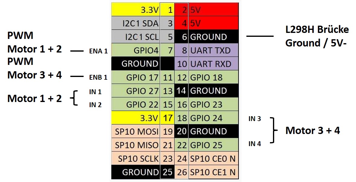
The next picture shows how I connected my motors and how I will control (speed / direction) them in future. I used the jumper names printed on the L298 H-Bridge to explain everything.
L298 H-Bridge PWM assignment
For the PWM signal please use the pins ENA and ENB which are in line with the pins IN1 to IN4.
- Motor 1
- ENA
- Motor 2
- ENB
L298 H-Bridge direction assignment
- Moto 1
- IN1
- IN2
- Motor 2
- IN3
- IN4
ATTENTION:
It is important to connect the for example the ground pin 6 from the Raspberry Pi with the ground from the L298 H-Bridge. On the L298 H-Bridge you can use the 5V – connector. This is important to ensure that the L298 H-Bridge knows what a high signal is and what a low signal is. If you do not connect the ground from the Raspberry Pi with the ground from the L298 H-Bridge normally nothing will happen.
The picture is a little bit different to the actual wiring. The Raspberry Pi is no longer powered over the L298 H-Bridge. The 5V out from the L298 H-Bridge was not stable enough to power the RaPi. I bougth a PowerBank for the Raspberry Pi. This is the reason why the picture is not correct in the upper left corner.
Raspberry PI – remote controlled car with a Raspberry Pi GPIO pin settings
The next picture shows how to wire the Raspberry Pi and the L298H Bridge.
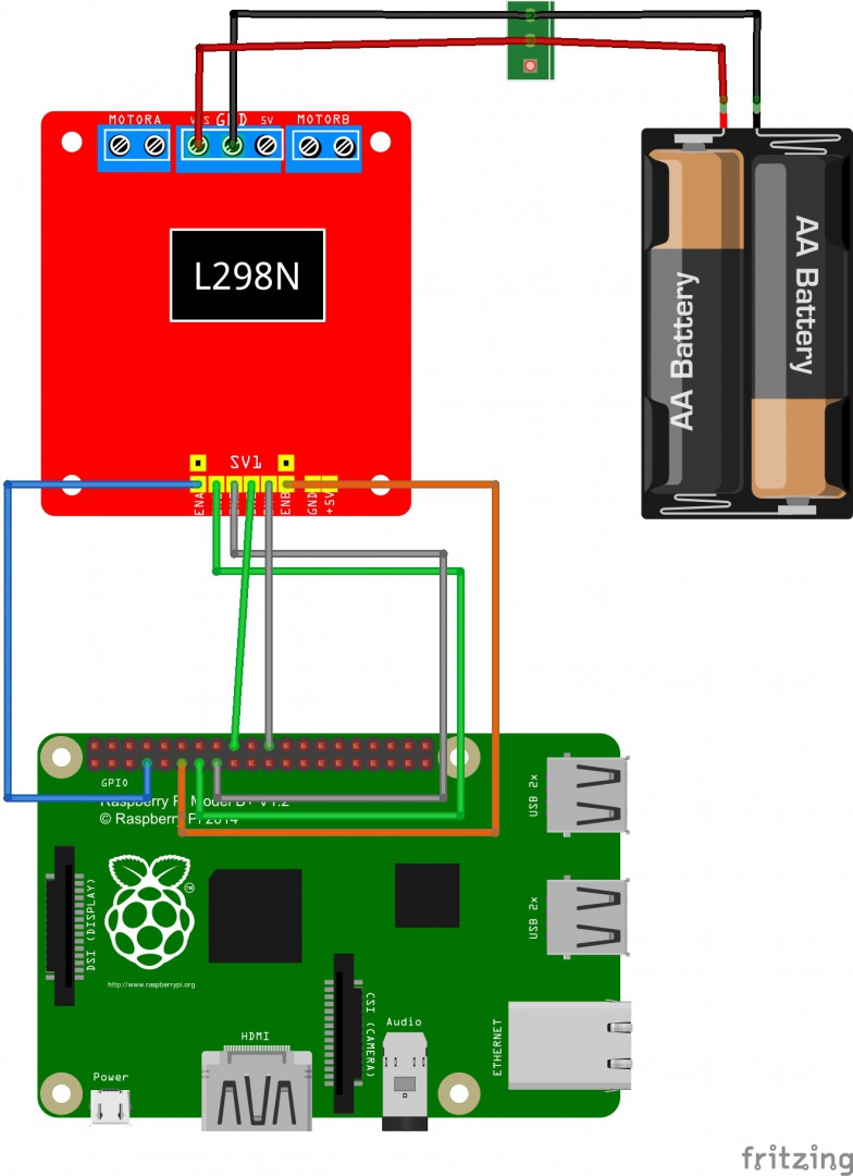
Raspberry PI – remote controlled car with a Raspberry Pi wiring motor driver
If the L298N H-Bridge is connected with the Raspberry Pi now the motors will be connected to the L298N motor driver itselfe.
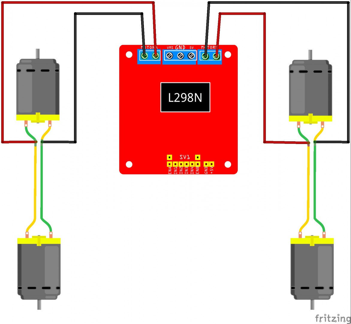
Raspberry PI – remote controlled car with a Raspberry Pi dc motor wiring
First I connected the Raspberry Pi with the 5V power supply to check if the PI works correct. Next I connected all wires as shown in the picture above.
It does not matter how you connect the ENA1 + ENA2 as well the ENB1 + ENB2 pins with the L298H Bridge. It is only important the ENA and ENB is connected as pairs. These pins are used for the PWM signal to control the speed of the motors.
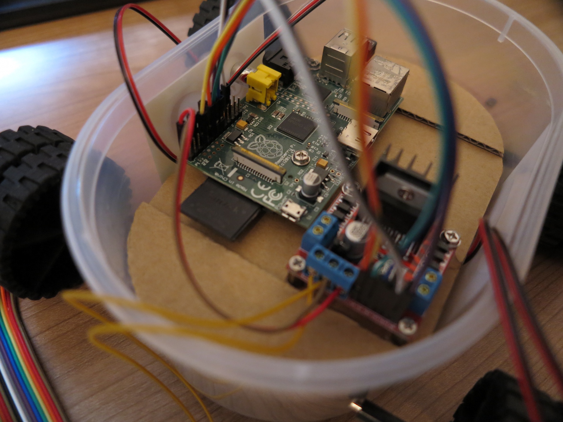
This picture shows the final setup of. Fortunately the wires are long enough to easily connect everything. I had no problems with the female to female wires.
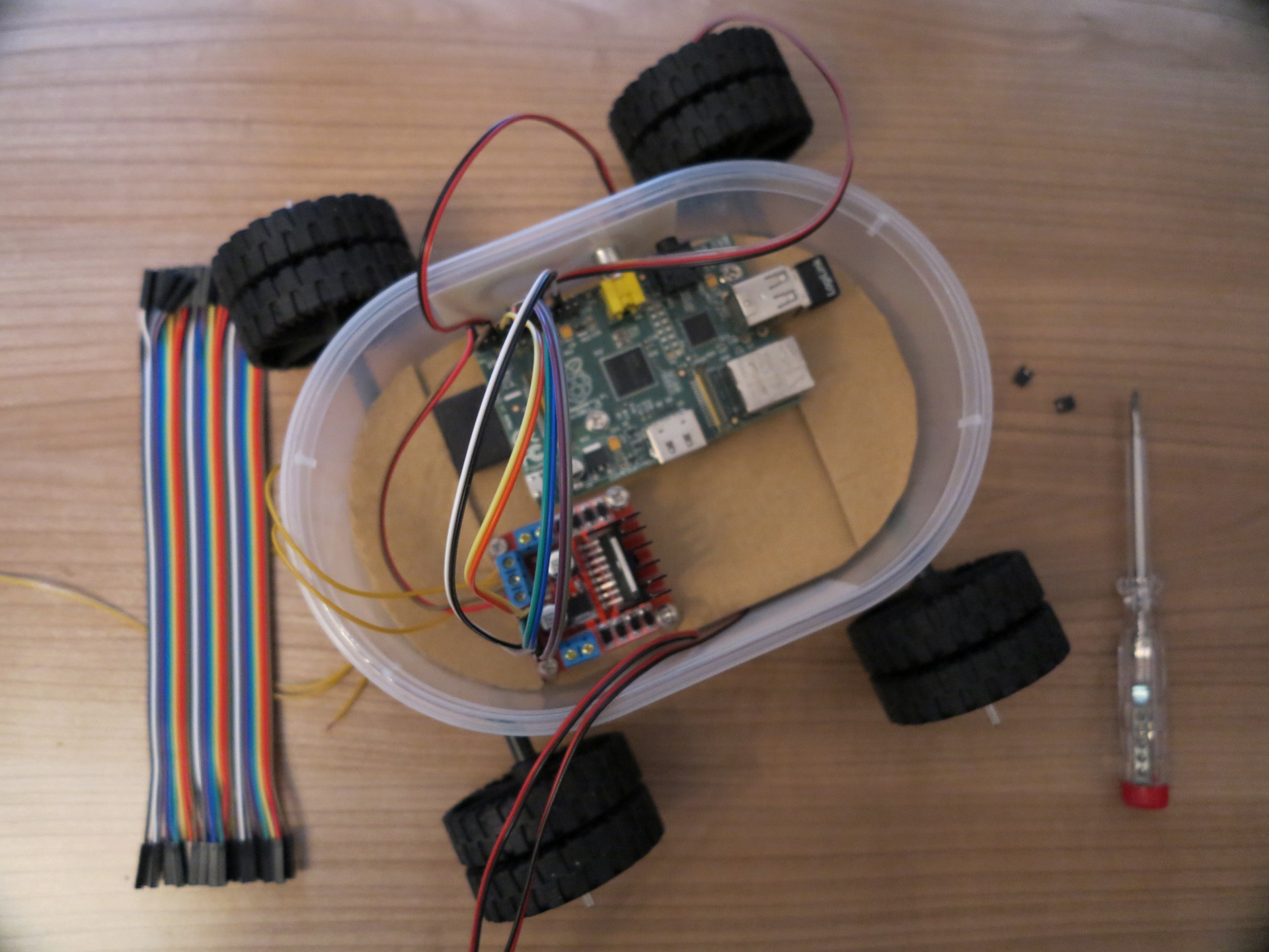
Raspberry PI – remote controlled car with a Raspberry Pi robot car
Conclusion:
Until now everything was easy and worked very well. You can save a lot of work if you buy female to female wires. The wiring is done very fast and you have no loose contacts which causes problems. In the first setup I powered the Raspberry Pi with the 5V out from the L298 H-Bridge. But as mentioned above this doesn’t work very well. The 5V out is not stable enough to supply the Raspberry Pi with sufficient and constant current.
The next chapter is about the software setup of the Raspberry Pi and what we need to program the first script to control the L298 H-Bridge and the four motors.
Contents:
Chapter 1: Raspberry Pi WIFI radio controlled rc vehicle – introduction
Chapter 2: Raspberry Pi WIFI radio controlled rc vehicle – component list
Chapter 3: Raspberry Pi WIFI radio controlled rc vehicle – chassis
Chapter 4: Raspberry Pi WIFI radio controlled rc vehicle – wiring
Chapter 5: Raspberry Pi WIFI radio controlled rc vehicle – software installation
Chapter 6: Raspberry Pi WIFI radio controlled rc vehicle – power supply
Chapter 7: Raspberry Pi WIFI radio controlled rc vehicle – programing
Chapter 8: Raspberry Pi WIFI radio controlled rc vehicle – live video streaming
Chapter 9: Raspberry Pi WIFI radio controlled rc vehicle – web-interface and smartphone
Chapter 10: Raspberry Pi WIFI radio controlled rc vehicle – cooling with passive heat sinks
Chapter 11: Raspberry Pi WIFI radio controlled rc vehicle – startup scripts
Chapter 12: Raspberry Pi WIFI radio controlled rc vehicle – cardboard car model
Chapter 13: Raspberry Pi WIFI radio controlled rc vehicle – power consumption


Wow! This is an awesome tutorial. The best I’ve seen.
I have a question. Due to fact that I have a PITFT on my robot and an Alamode also
both devices take up pins that you use in your rapi-car script. I have had tp switch
to WebIOPI after looking at other ways of finishing my R2 unit
This is where I have had to stop due to my lack of programing skills
https://www.youtube-nocookie.com/watch?v=m7WNfRtMux0
All I need is a little help getting the motors to play nice
and a servo going. Where can I buy your book.
I would like to know can I use pins 4,17,22 and 23 or 4,17,27,22 to control the motors
using a L298 hbridge with no speed control. does this look right?
motor1_in1_pin = 4
motor1_in2_pin = 17
GPIO.setFunction(motor1_in1_pin, GPIO.OUT)
GPIO.setFunction(motor1_in2_pin, GPIO.OUT)
motor2_in1_pin = 22
motor2_in2_pin = 23
GPIO.setFunction(motor2_in1_pin, GPIO.OUT)
GPIO.setFunction(motor2_in2_pin, GPIO.OUT)
Hi Alden,
your R2 robot looks very coool.
This looks right. If you use no PWM signal to control the speed of your R2 you can use the pins as described from you.
Actual the book is only in German and I am reworking / reviewing the book. I let you know when I have finished the book.
Maker
Thank you for the advise. I also would love to see your book in english !! I believe many would. Your tutorial on this web site is very well played out. I have read many .
I have a big doubt, you wire the 12V ground to the raspberry pi, it doesn’t kill it?, because the raspberry pi doesn’t support a voltage higer than 5V, if not, you can explain it to me?.
No, I am using a 5V PowerBank to power up the Raspberry Pi. Only the ground of the PowerBank and the ground of the 12V Battery is connected with each other. That does not kill your Raspberry Pi.
Hi,
your project is realy cool. i will probably use some informations for my explorer robot project.
in your wiring and the corresponding python script, something seems strange about the enable pins. L298n has only 1 enable pin for each channel so one enable_A and one enable_B.
am i wrong ?
thank you.
Hi Lerva,
no that is fine. You only need one pin on the motor controller to activate for example the channel A.
Regards,
Maker
Hi,
My raspberry pi is 3 model B, The L298H bridge ENA1+ ENA2 & ENB1+ ENB2 total 4 pins, How to connect
GPIO pin , And use PWM to control motor speed, Because the above explanations and pictues not clear.
Thank you,
Ich habe eine Frage: Ich habe mir, wie in der Englischen Komponenten Liste beschrieben ist, das folgende Kabel bestellt:
https://www.amazon.de/Kfz-Leitung-Anh%C3%A4ngerleitung-Meterware-Rundleitung/dp/B00HXU66NA?psc=1&SubscriptionId=AKIAJBIBFNKTI6MUYGPQ&tag=ingmstap-21&linkCode=xm2&camp=2025&creative=165953&creativeASIN=B00HXU66NA
Nun habe ich keine Ahnung wie ich mit diesem Kabel die Komponenten verbinden soll. Mein Kabel ist sehr dick und es ist zwar zweiadrig, aber auch die zwei “Adern” sind viel dicker als deine Verbindungen. Und kann man überhaupt die female-female Jumper ohne Probleme vorne abschneiden? Oder hast du es so gemacht?
Ich bitte um Aufklärung, danke.
PS: Sorry, falls die Frage extrem dumm ist, eine Antwort wäre aber trotzdem nett 🙂
Hallo Marvin,
ich vermute sehr stark das Du den falschen Querschnitt bei dem Kabel erhalten hast. Dieser kann auf der Amazonseite ausgewählt werden.
Viele Grüße,
Maker
Danke, ich werde nochmal nachschauen.
Welchen Querschnitt benötige ich denn? Es steht nichts in der Anleitung.
Hallo. Wie auch Marvin benötige ich den Querschnitt des Kabels, da er nicht in der Anleitung steht und ich mir nicht, wie Marvin, das falsche bestellen will.
Hallo Tim,
ich verwende für kleine Modellmotoren immer einen 0,14 mm Querschnitt. Das reicht eigentlich ganz gut aus.
Ich habe alle Komponenten unter folgender URL zusammengestellt. Dort findet Ihr auch den Querschnitt angegeben.
Komponentenliste
Viele Grüßer,
Maker
Danke für die Antwort. Ich habe nur die englische Komponenten Liste gelesen und dort steht ein anderes Kabel und ein anderer (undefinierter) Querschnitt. Trotzdem danke.